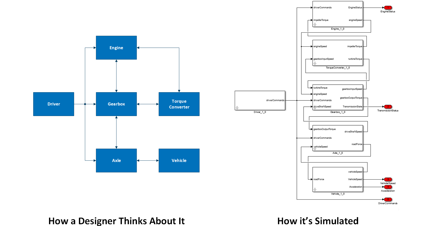
The steps are:
- Draw an abstract block diagram that shows the components.
- Draw connections between components. For this block diagram, these connections are simple abstract lines connecting components, without any connection details.
- For each connection, create a separate drawing to illustrate the connection details
- Reorganize the information into ICDs.
This process is not as linear as the above list suggests. As you work on the details, you might discover the need for connections, components, or connection details that you hadn’t initially considered. This is okay; any step can be re-visited as needed. Also, as the project progresses, the level of fidelity will increase, and all of these steps should be revisited for each design update.
Draw an Abstract Block Diagram that Shows the Components
Conceptually, this step is really simple: Draw some blocks with labels:
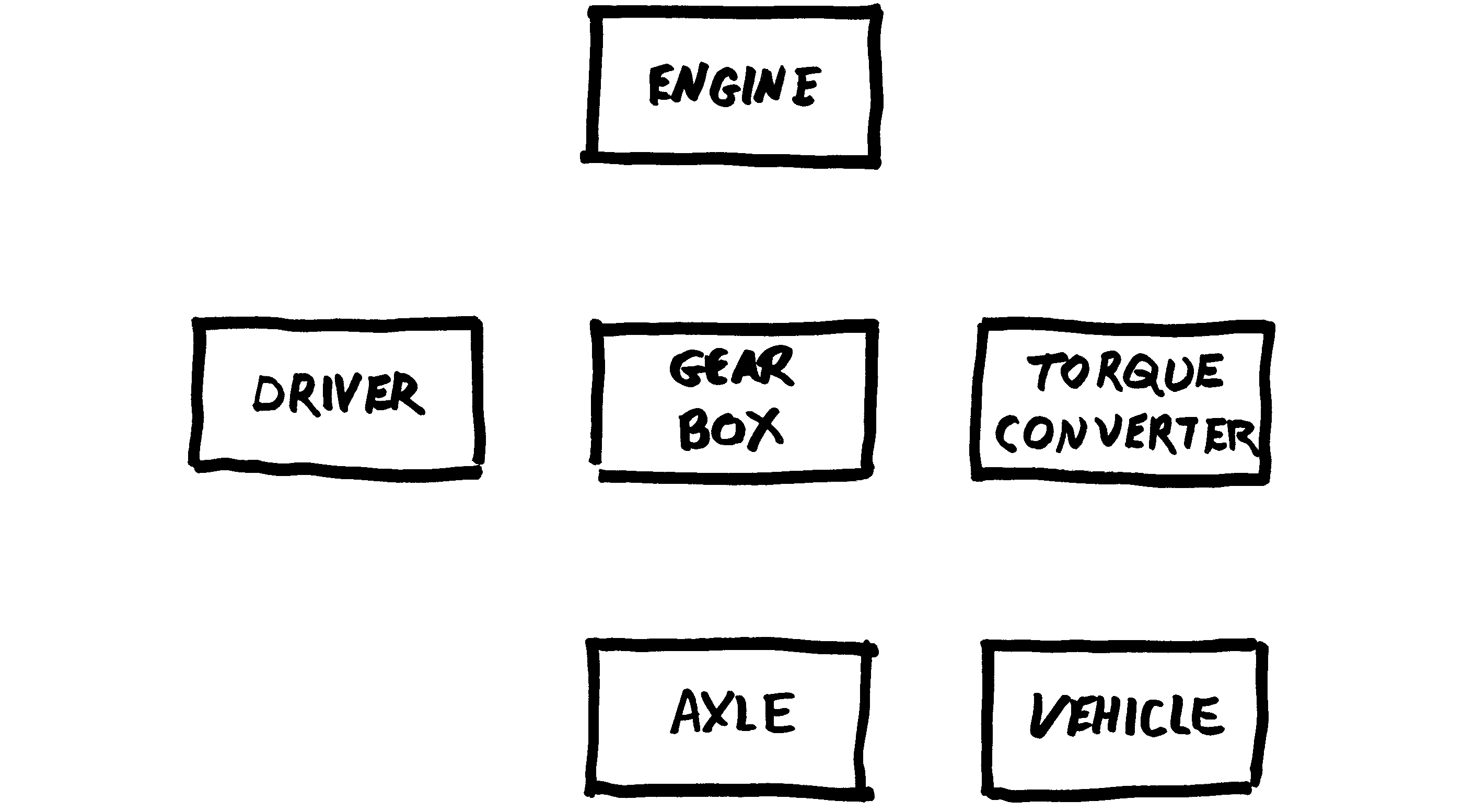
- The expected contribution from each group. For example, your engine controller might be part of an embedded software group, or it might be part of a vehicle controls group.
- The complexity of the simulated system. For example, for a simple machine with just one hydraulic ram, it might make sense to model the pump, the valve, and the ram as a single component. However, for a commercial passenger jet, the hydraulic elements should probably be modeled as separate simulation components.
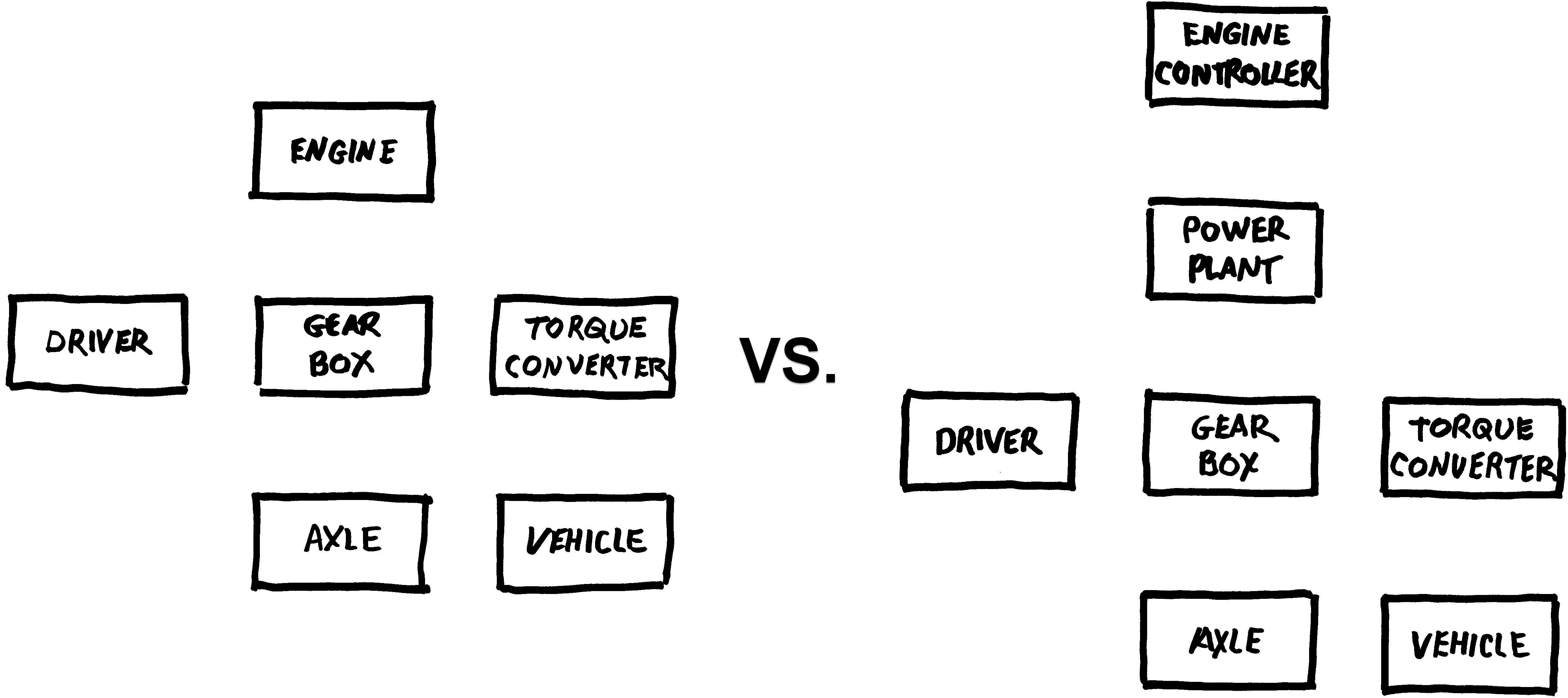
- The level of fidelity. For example, a low-fidelity drive train simulation might combine the powerplant and the engine controller, while a high-fidelity simulation would model them separately:
Draw Connections Between Components
The goal of this step is to illustrate connectivity, not to show data flow or low-level details.
Again, this step is easy to understand, but requires engineering judgement based on your project’s goals.
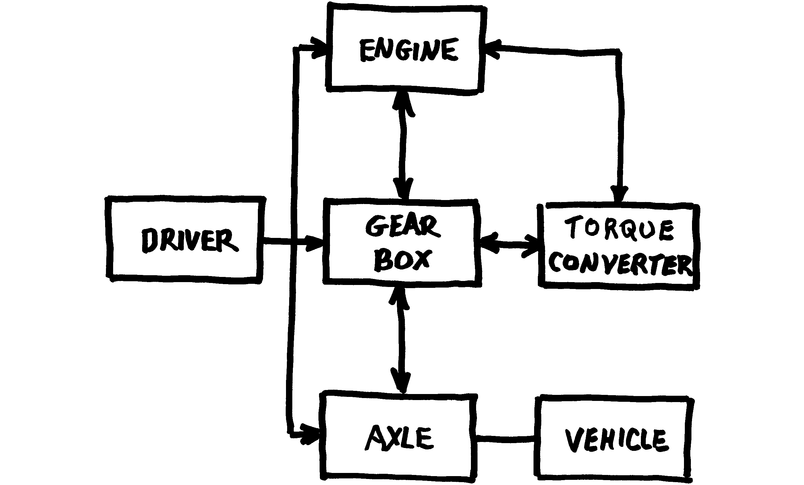
The connections you draw will depend on issues such as:
- Your selection of components. If you choose to combine the powerplant and the engine controller into a single component, you won’t be drawing connections between the powerplant and the controller.
- Your level of fidelity. A high-fidelity spacecraft simulation might consider thermal interactions between components, but a low fidelity simulation might not.
- The topology of the simulated system. If your vehicle is controlled by a single central microprocessor, then most components will connect to it. If your vehicle is built from stand-alone off-the-shelf subsystems, then there might not be connections to a central microprocessor.
With the connections drawn, the block diagram is a good high-level illustration of the simulation.
Remember that this is not a linear process. You are free to add or remove components while you are drawing connections.
Create Drawings to Illustrate Connection Details
For each of the connections in your drawing, create a detail drawing showing the actual low-level simulation connections between the components:

For each physical modeling connection, the diagram must indicate:
- Name
- What physical modeling domain is represented (thermal, mechanical, electrical, etc.), and
- Units (this might be implied by the physical modeling domain)
For each data signal, the diagram must indicate
- Name
- Date type (float, integer, data structure, etc.)
- Timing (continuous time, discrete time, inherited timing, etc.)
- Units (kg, m, counts, LSBs, etc.). If the units are radians, this must be indicated to prevent confusion with other non-dimensional signals.
- Direction (use arrows to indicate the direction of data flow)
For some simulation engines, the name is not strictly required. However, a name is an important tool in conveying meaning.
Because these are low-level details, you should probably get input from the contributing groups. This would result in technical negotiations between the groups on the signal definitions.
At this stage of the design process, the differences between a project within your own group and a Distributed MBD project become very pronounced:
| Internal Project | Distributed MBD Project | |
| Precision and Accuracy | Not as critical. Errors can often be ironed out informally between the engineers within your office. | Precision and accuracy are critical:
|
| Completeness | This step might not be needed. Depending on your engineers’ skill set, they might be able to determine the signal definitions between themselves, without your intervention. | This step is mandatory. It defines how each group will build their respective components. |
| Detail | As a project leader, you might not want to worry about these low-level details, and instead delegate this step to your engineers | You must concern yourself with these low-level details. As a project lead, you are responsible for coordinating the different groups. Coordinating dispersed groups requires that these details be ironed out centrally. |
With the low-level signals defined, you have all of the information that should go into the ICDs. However, this information is not in an ICD format.
Again, you are free to go back to the high-level diagram to change connections and components while you are specifying low-level details.
Notice that these steps help you focus on different portions of the design separately. By identifying connections at the high level, and providing connection details at a lower level, you focus on each aspect of the design separately instead of trying to capture everything in a single unified drawing.
Create the ICDs
This step is a matter of bookkeeping, and not really an engineering effort. At this point, you have diagrams of the system from the designer’s point of view, and you just need to re-organize it into the component developers’ point of view in the form of ICDs.
For each component:
- Compile a list of the high-level connections for that component,
- Expand each element of that list into the low-level connections to the component.
When expanding the list, you must retain this information:
- Whether it is a physical modeling connection or a data signal connection,
- The domain of physical modeling connections,
- Units,
- Data type,
- Timing, and
- Direction.
When conveying the direction information, a simple flag indicating whether it is an input or an output will suffice.
For some simulation engines, you might need to also define connection ordering. In Simulink, the input ports and output ports of a Simulink block diagram are ordered, so you should specify the order of the inputs and outputs. Most source-code based simulation engines use function calls, so the function names essentially become the connection names, and ordering is not important.
Distributing the ICDs
When distributing the ICDs to the various groups, it is important that you emphasize that the design is dynamic. It is important for all groups to understand that:
- Although the initial ICDs are your best effort, they probably have room for improvement. As the teams begin implementing the components, they might discover issues with the design. This could be the discovery of some arcane signal that had not been previously identified, a better choice of units, or a re-organization of the signals. This is okay and expected (and will be resolved by the next bullet point).
- Re-negotiating based on new information is not only encouraged, but it is critical to the success of the project. When an engineer discovers the need to update the interfaces between components, this should be elevated to your level promptly, so that it can be addressed early. You don’t necessarily need to respond to it personally, but you should at least initiate a technical re-negotiation between the affected groups. This will also give you some indication of whether some group is trying to implement higher fidelity than the other groups are ready to support, given the level of maturity of your project.
- The initial set of ICDs is only a starting point, and the design will evolve as the project progresses. As the teams learn more about the simulated system (and the simulation itself), the design will evolve accordingly. Also, as simulation fidelity increases, the design will be updated as needed.
SystemBlend™
SystemBlend™ automates the above process. The SystemDesigner desktop application has drawing tools to capture the information described above.
The Design Pane is used to draw the components:
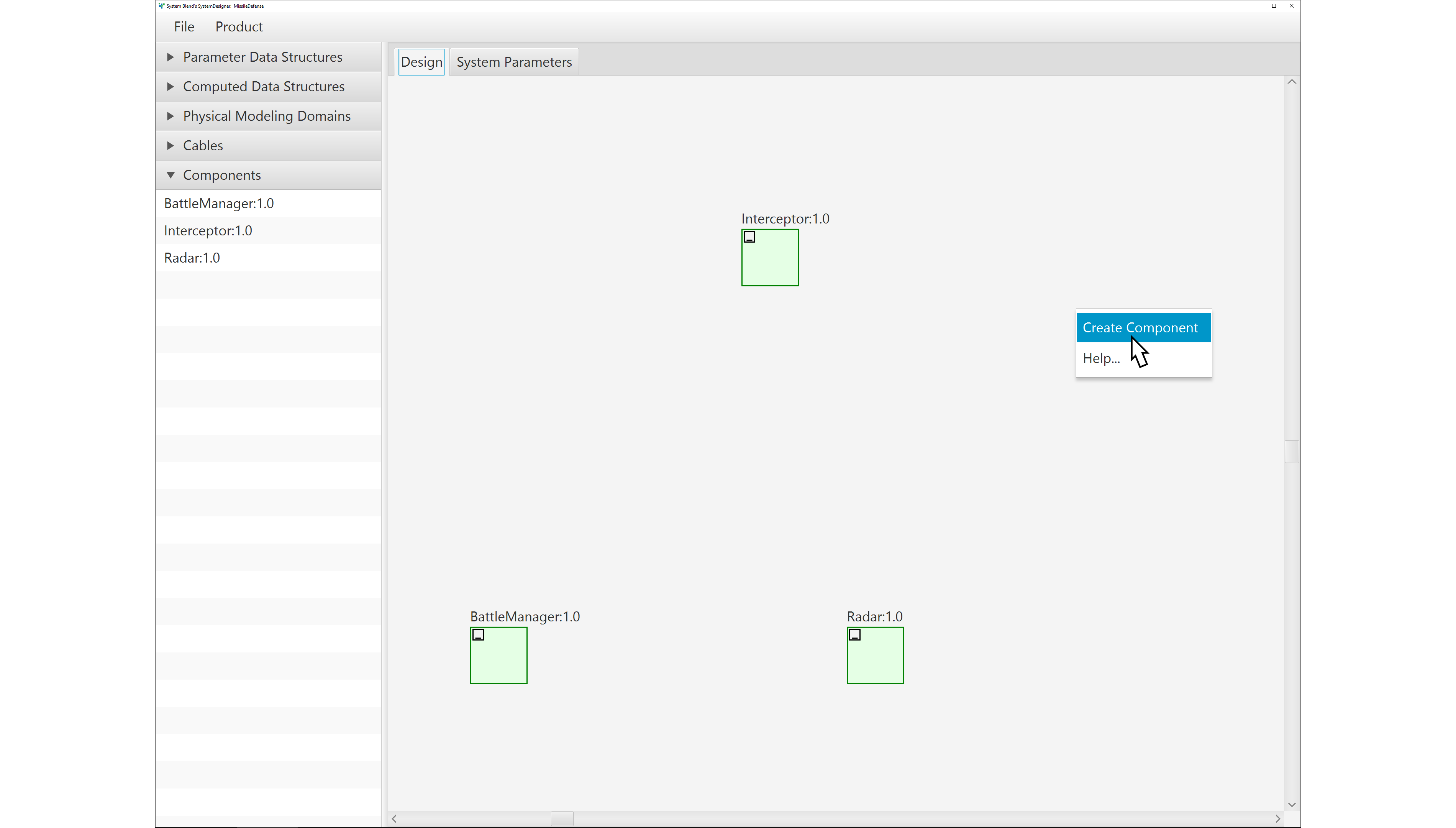
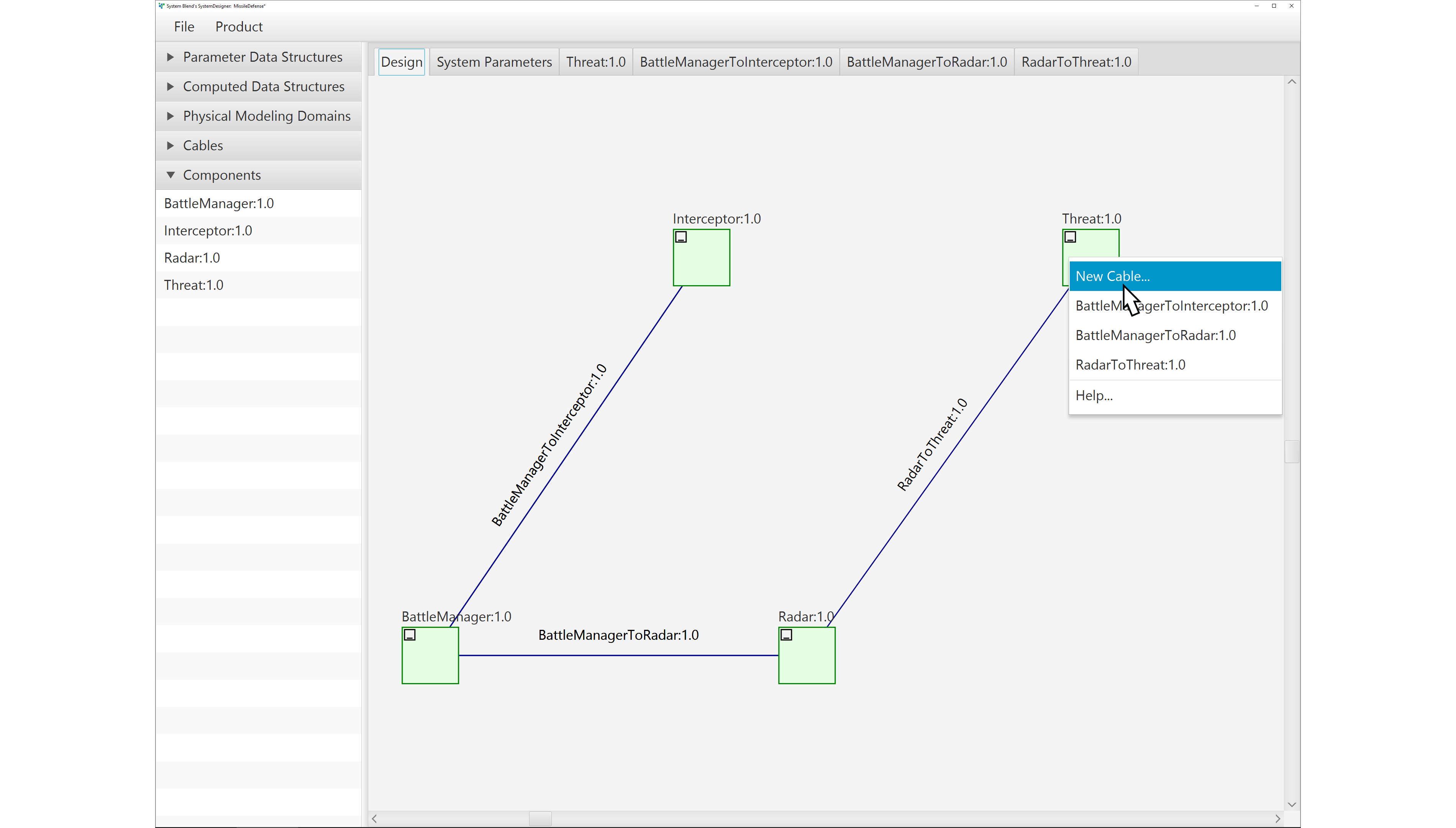
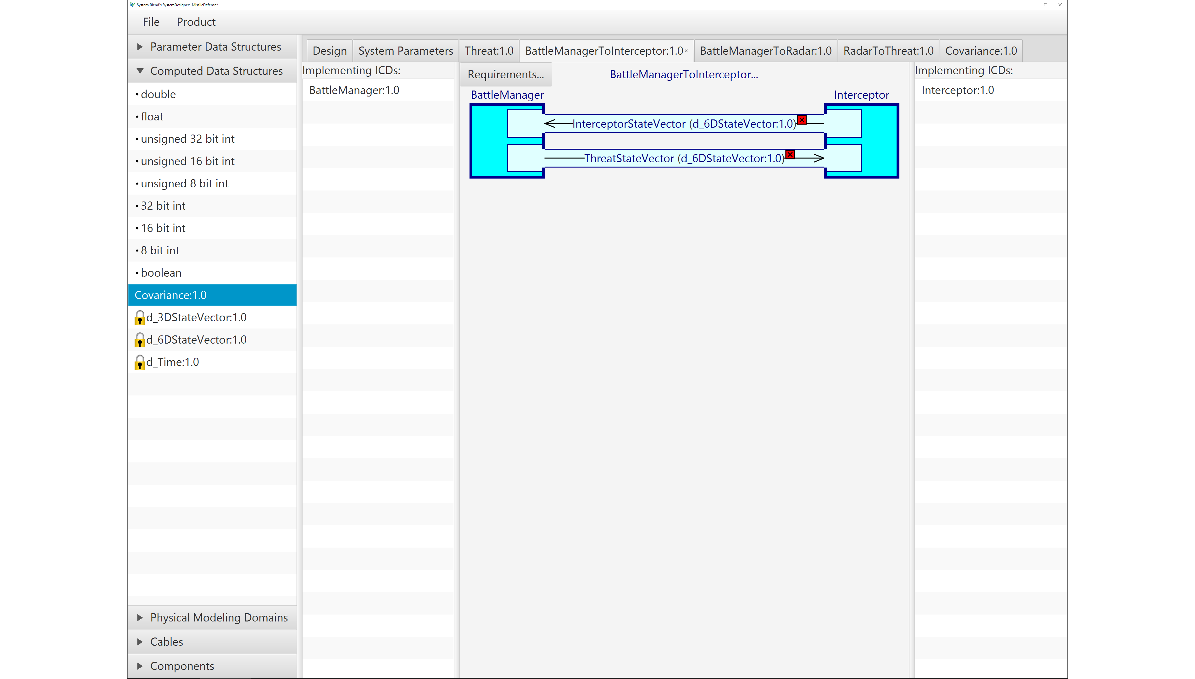
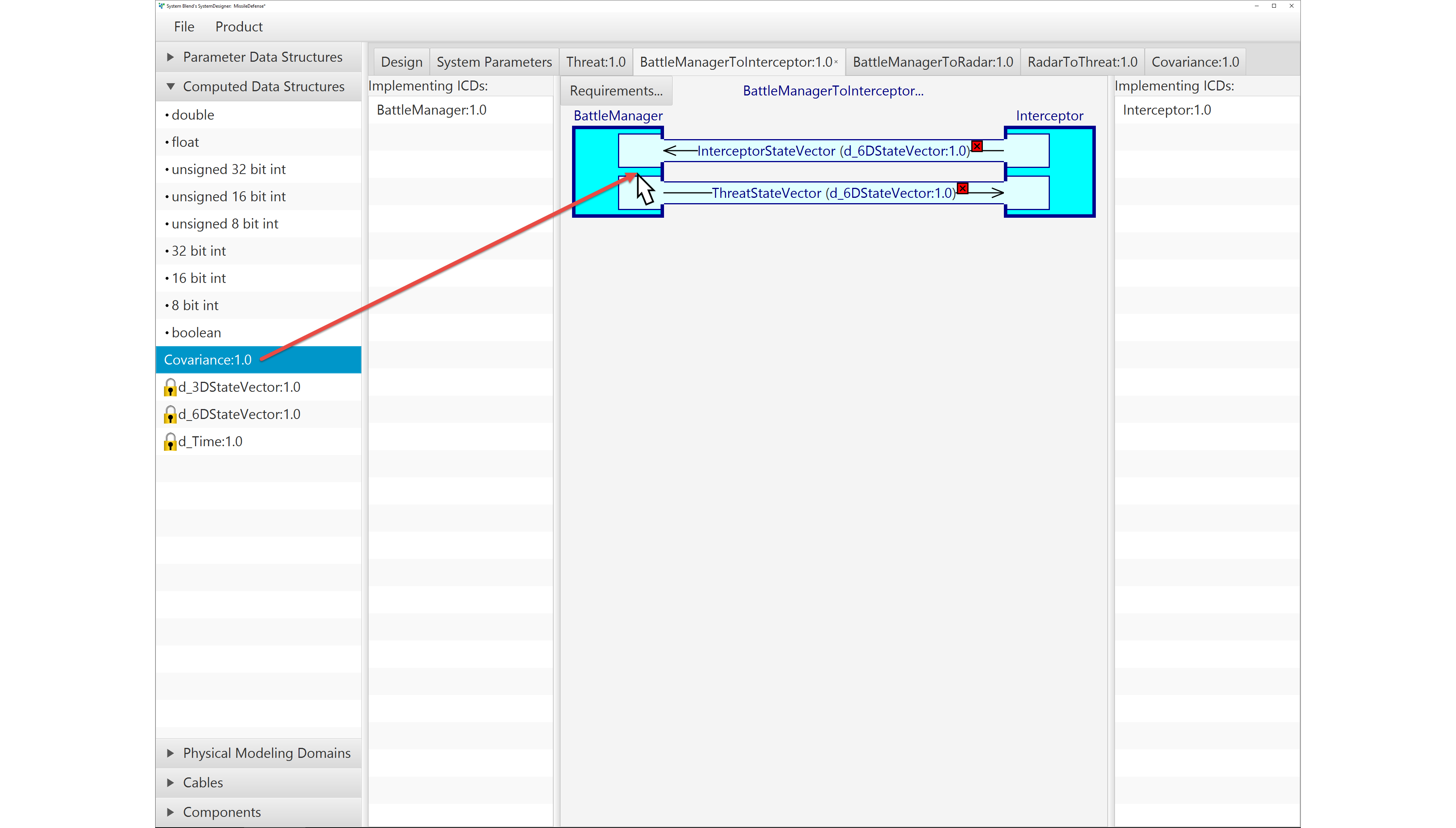
SystemDesigner is a free-form design capture tool, and does not impose any particular order to the steps. This means you can add components, modify connections, and edit connection details in any order.
SystemBlend™ automates the design capture, as described above, but it also does much more. Using the information captured in the drawings, SystemBlend™ will:
- Assist the component developers in implementing the ICDs,
- Ensure the contributing groups accurately follow the ICDs, and
- Automate the integration of the components into a working simulation.
