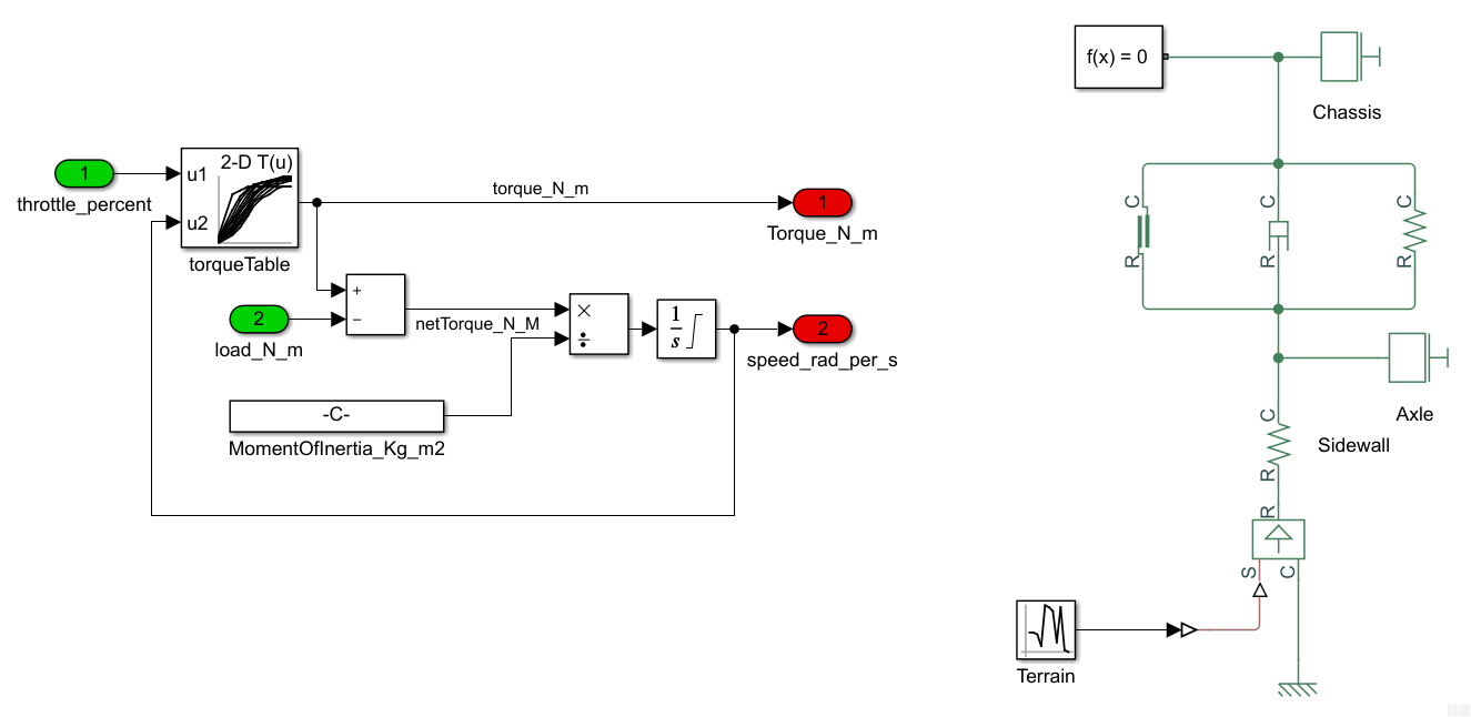
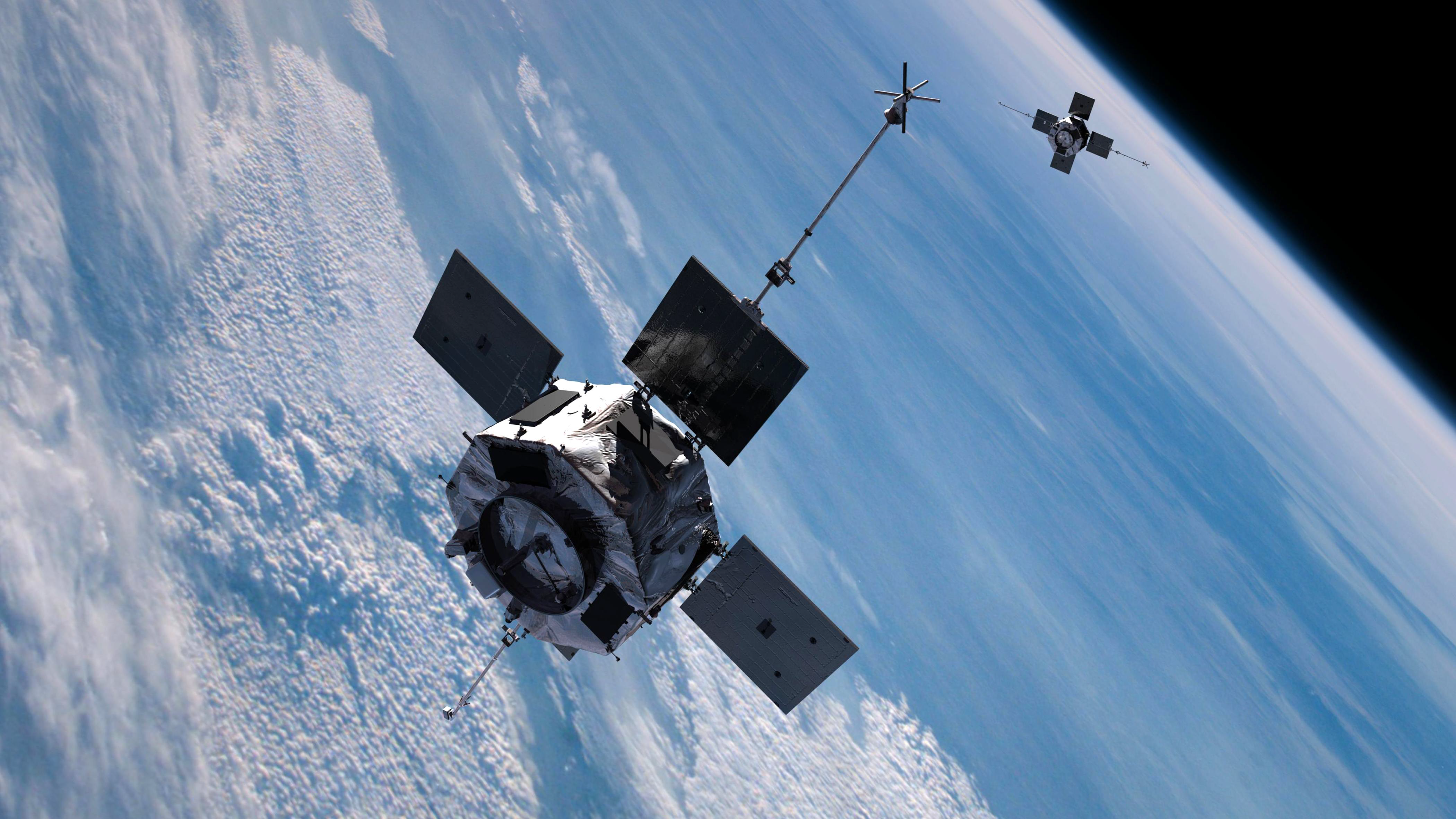
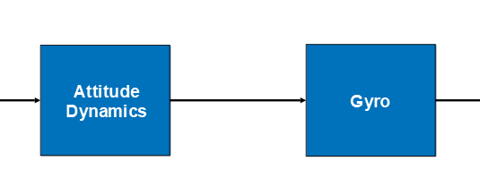
Signal-based modeling works well for systems that can be readily defined by input-output relations. For example, consider a simulation of a spacecraft’s attitude dynamics:
Unfortunately, not all systems can be readily defined as input-output systems.
I’ll define Physical Modeling simulation as a network consisting of components with connections that establish relationships between components. These relationships are not directional and do not directly have a value. Instead, they link physical values between components such as pressure and volume, or voltage and current. The behavior of these physical values is defined collectively by the connected components. This type of modeling is exemplified by Modelica object diagrams or Simscape diagrams.
Most physical systems with discrete components can be simulated with physical modeling, including those that have input-output relationships. A simple automotive drive train can be modeled using signal-based modeling, but to do this you need the counter-intuitive realization that the central component in the modeling is the torque converter. On the other hand, a drive train can be intuitively modeled with physical modeling techniques.
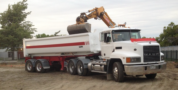
Some physical systems are very difficult to define using input-output relationships. Consider a simulation of the body dynamics semi tractor-trailer:
Some real-world components are purely input-output devices, such as the attitude control computer mentioned above. These components should be modeled with input-output relations. Fortunately, signal-based modeling systems can interact with physical modeling systems, allowing hybrid simulations that include both types of modeling.
Note: The above definitions and descriptions are neither precise nor complete, and there are much better definitions in the literature. Instead, I’m merely trying to convey some of the key differences between these two forms of simulation.
Distributed MBD Projects
One of the keys to success in a distributed MBD project is clear, precise, and unambiguous communication between the groups. From this point of view, there are advantages to each style of simulation.
With signal-based modeling, precisely defining the technical aspects of connections between components from different groups is a little easier. For example, it is very easy to declare that the angular velocity output on the component from the attitude dynamics group should connect to the angular velocity input on the component from the gyro group:
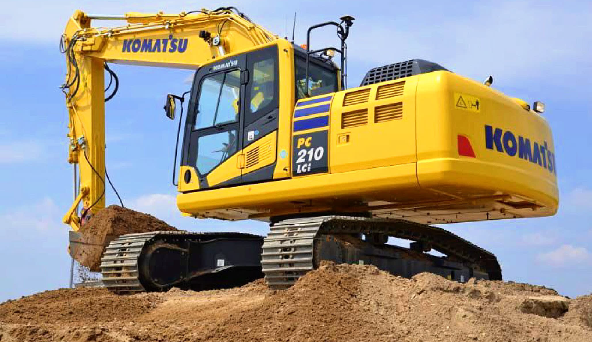
With physical modeling, describing connections between the components from different groups is a little more intuitive. Consider a hydraulic system:
SystemBlend™
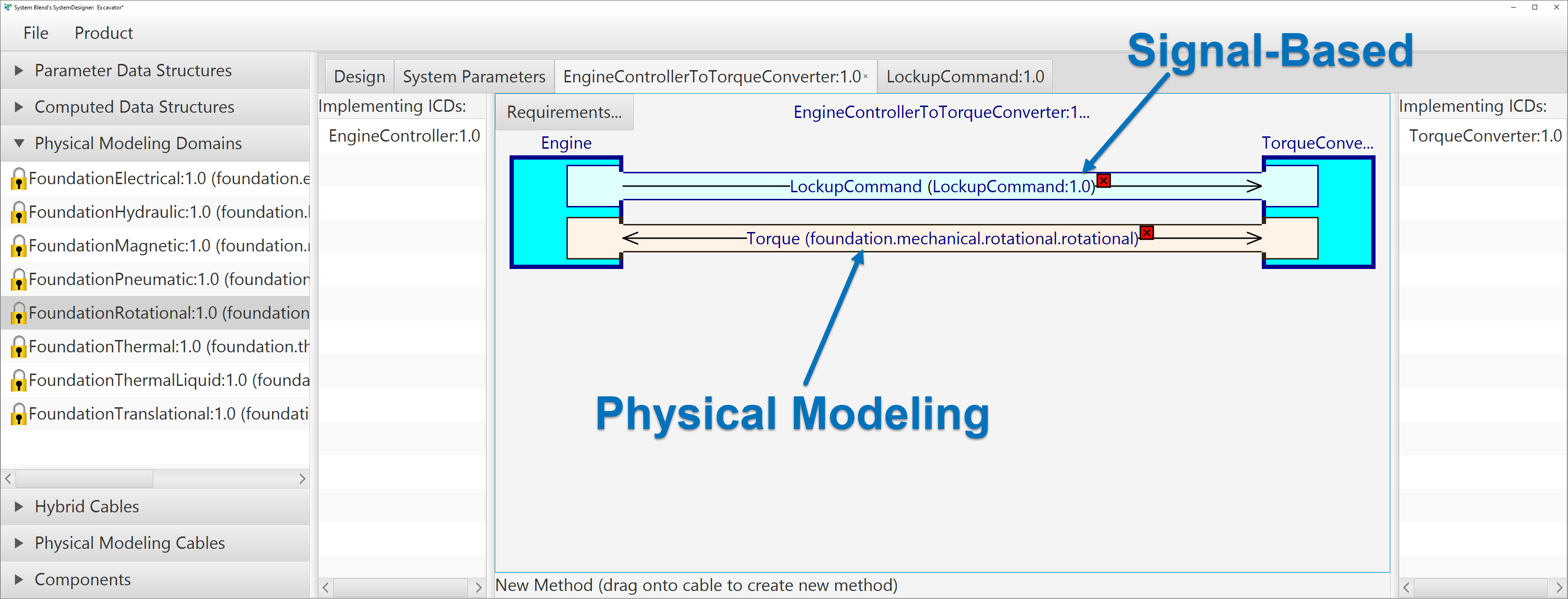
Both signal-based modeling and physical modeling are fully supported by SystemBlend™, including custom-defined physical modeling domains.
A physical modeling connection can be included in a cable, alongside signal buses:
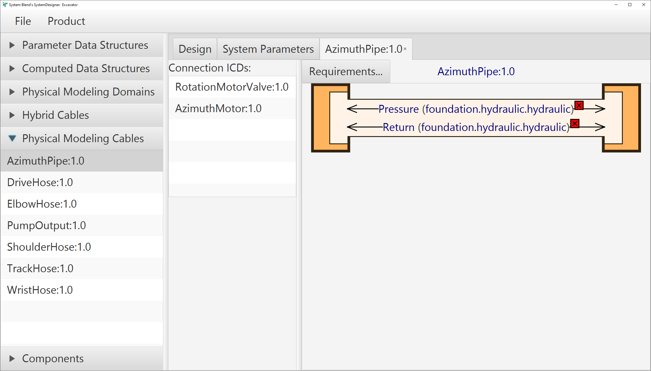
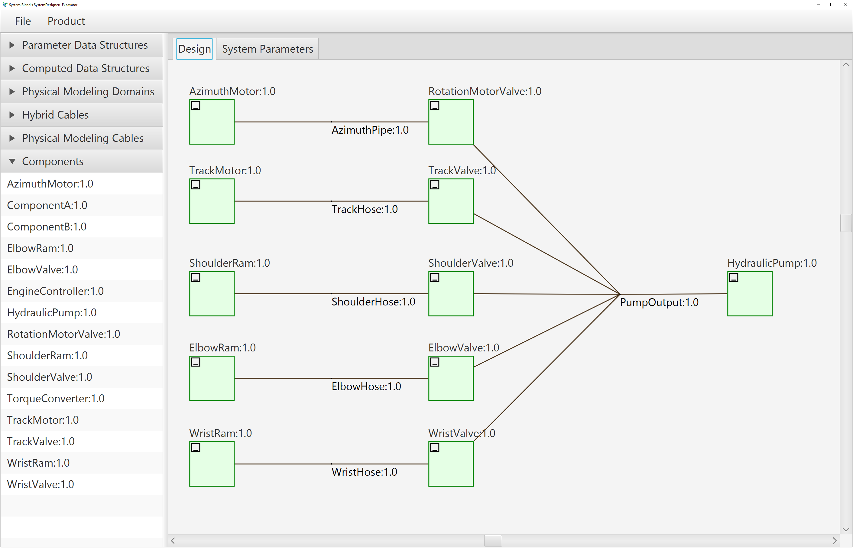
Physical modeling is not necessarily point-to-point, so SystemBlend™ also includes a style of connection that is purely physical modeling:
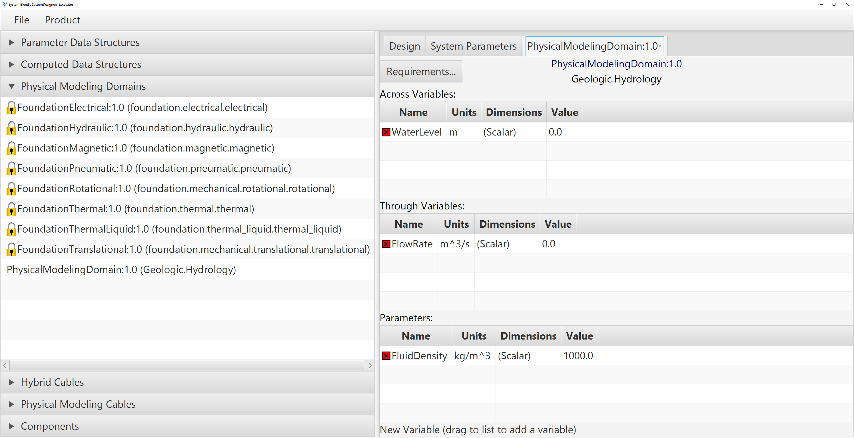
Custom physical modeling domains can be defined with simple drag-and-drop in the GUI of the SystemDesigner desktop application:
