This is first of a three-part series describing SystemBlend and how it works. For this article, I’ll describe SystemDesigner.
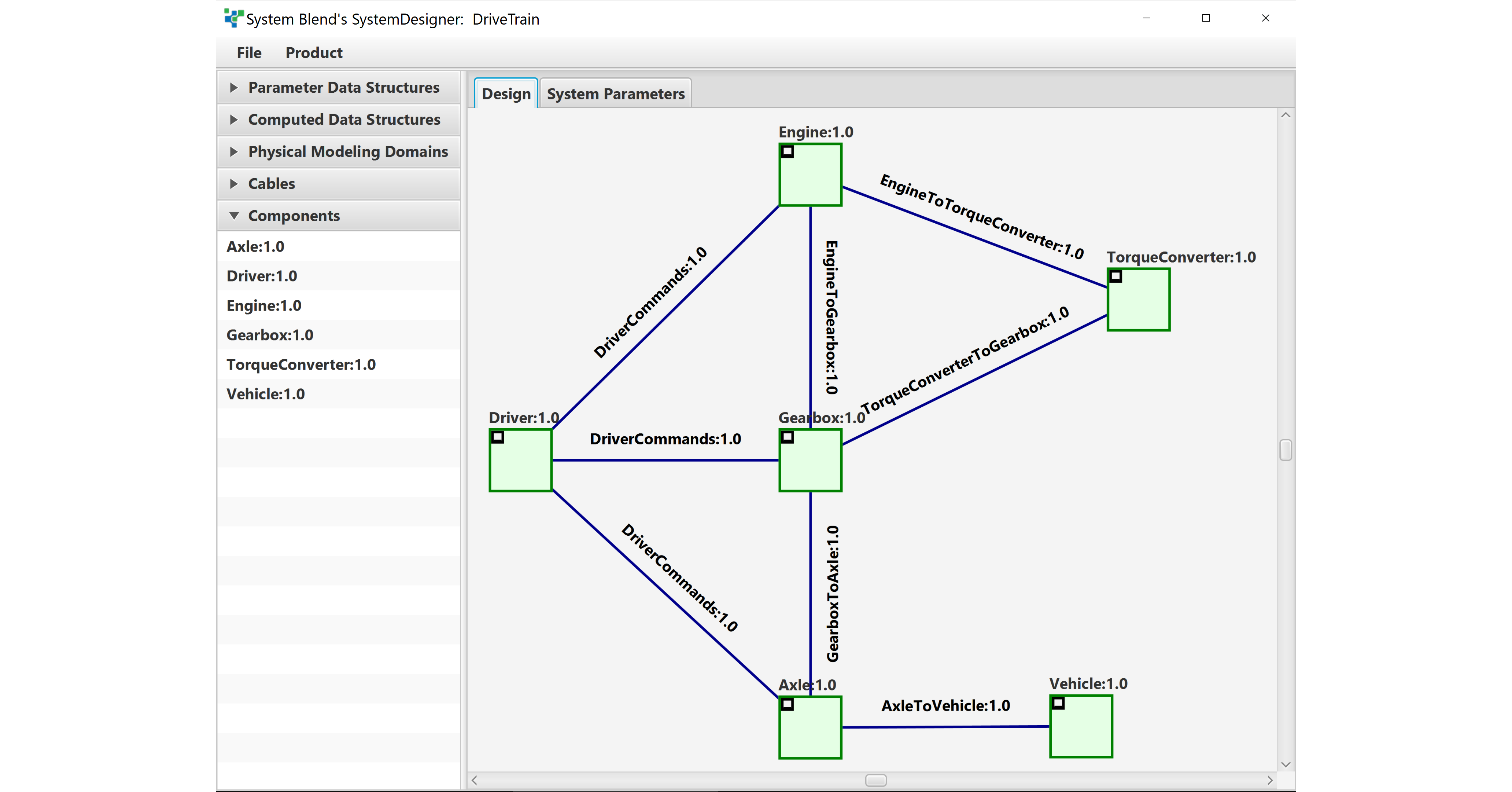
Imagine you’re managing a simulation project, and you will be combining subsystem models from different organizations. You capture and edit your design with SystemDesigner, part of the SystemBlend application suite.
Naturally, you’ll want input from all of the stakeholders, especially from the groups that will be providing subsystem models. To facilitate this, arrange a teleconference with the stakeholders, and share the SystemDesigner screen:
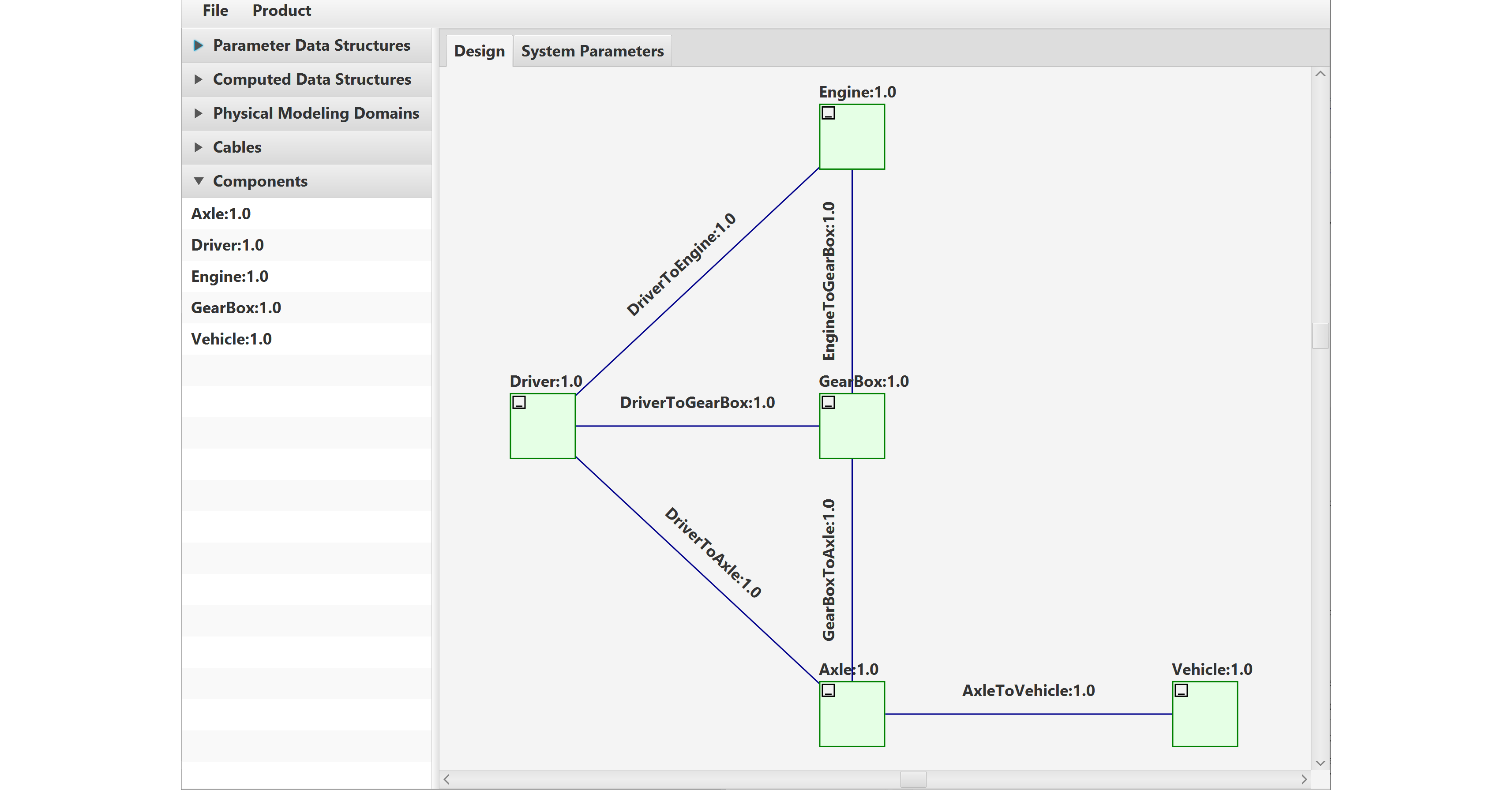
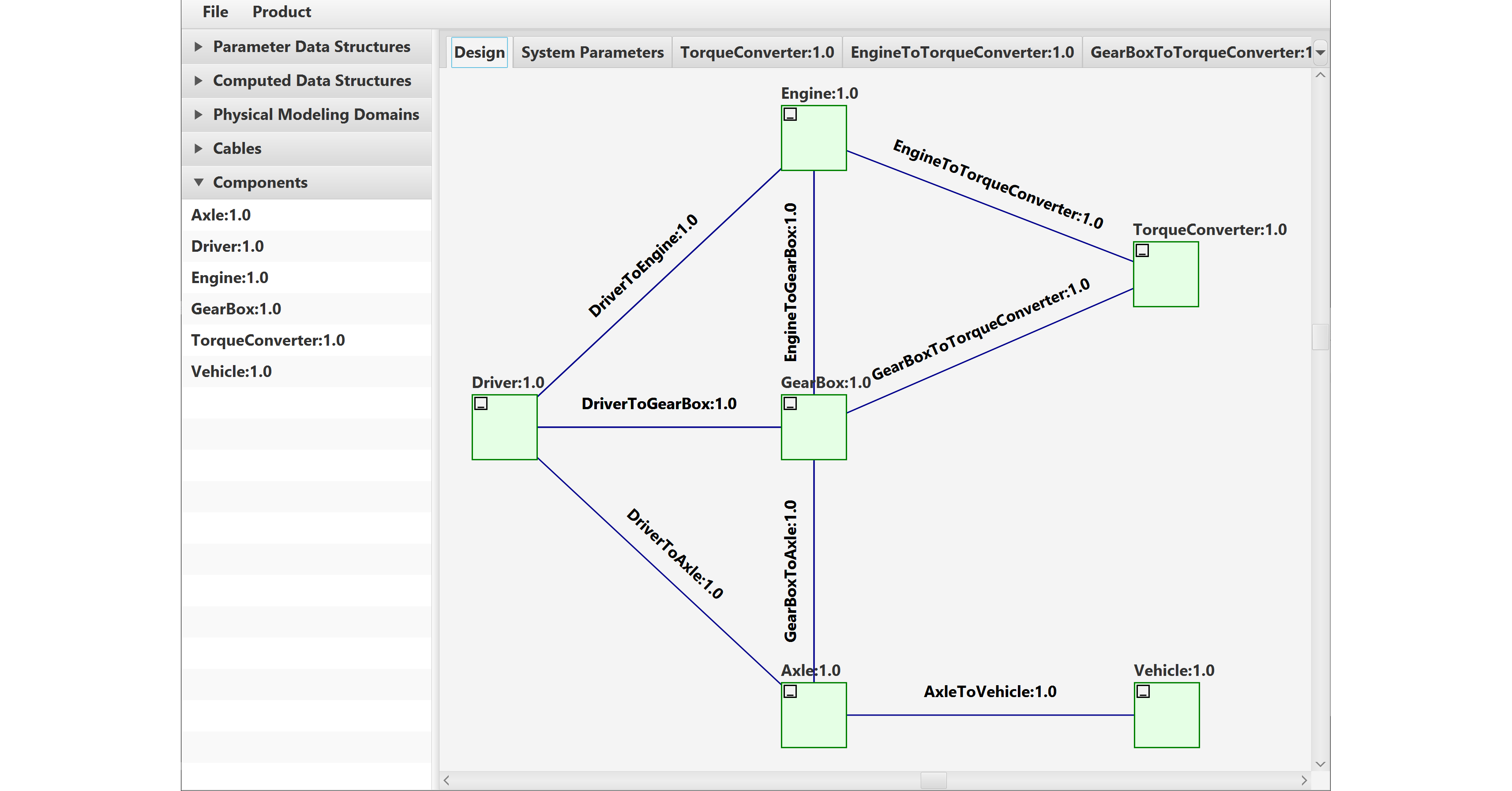
SystemDesigner is a free-form tool, meaning there is no set order of operations, but typically you would start by graphically defining the components:
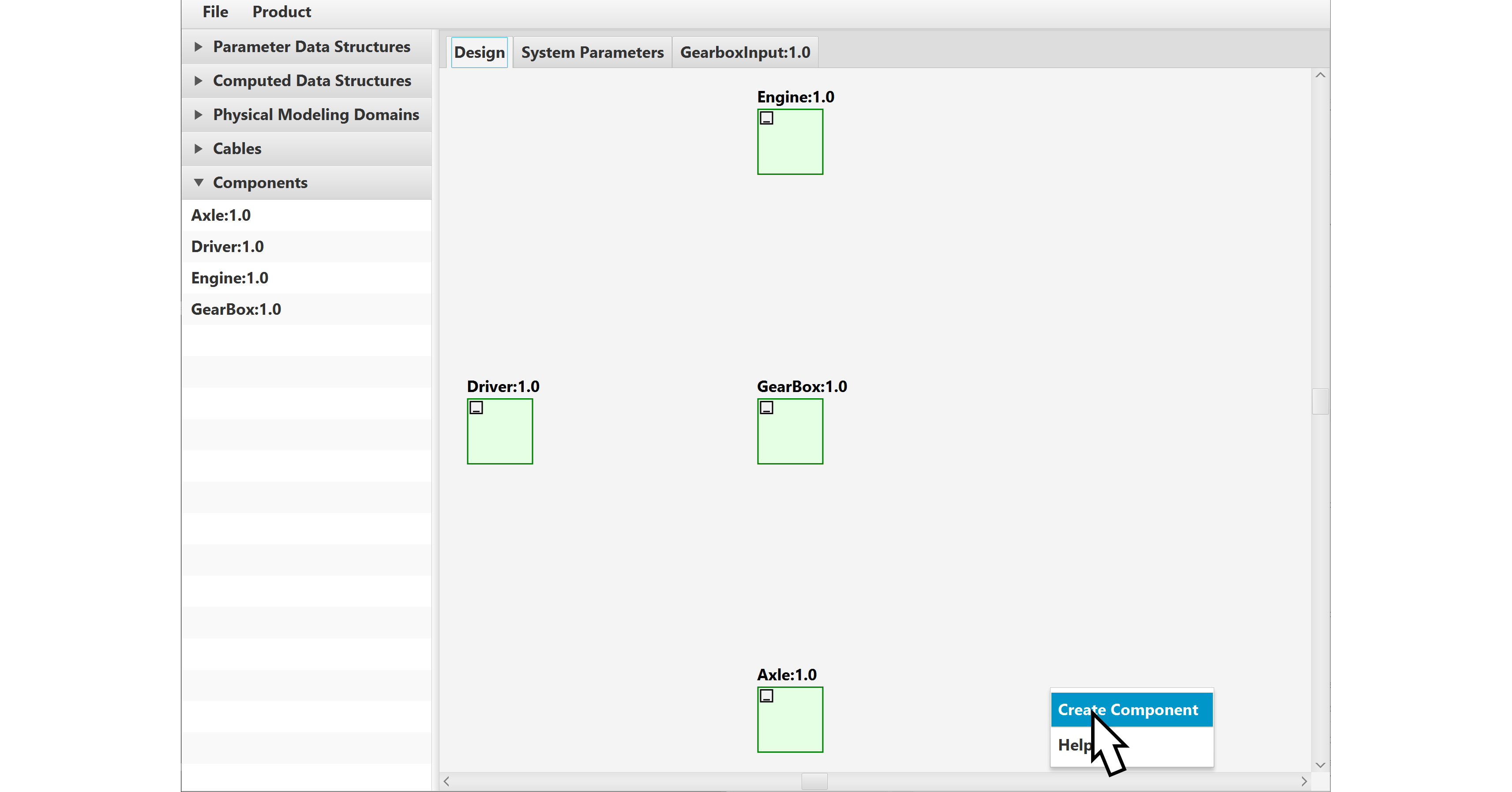
Once the components are defined, you define connectivity between the components by drawing cables between them using drag-and-drop:
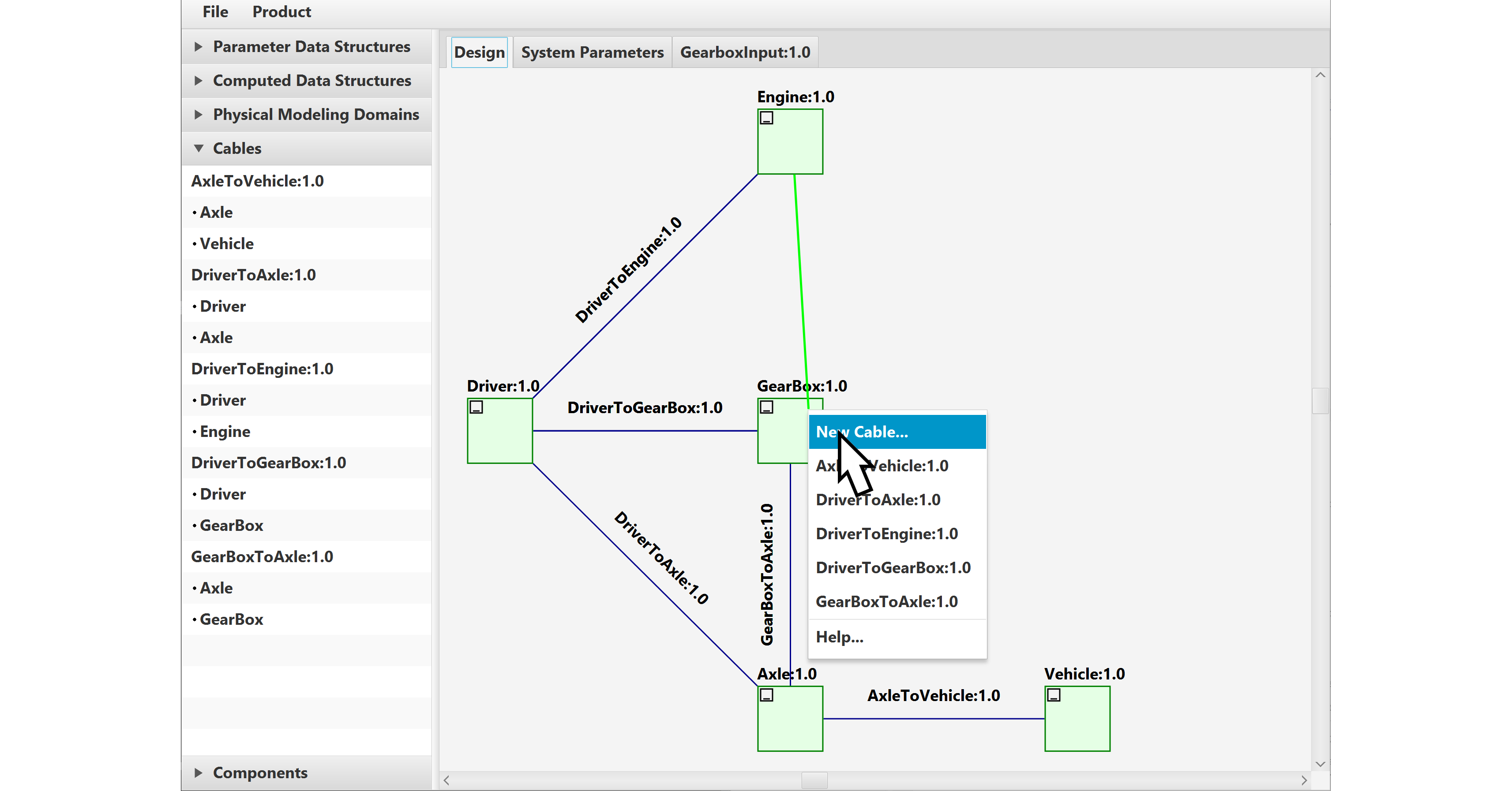
Open up a cable to specify the data that it carries:
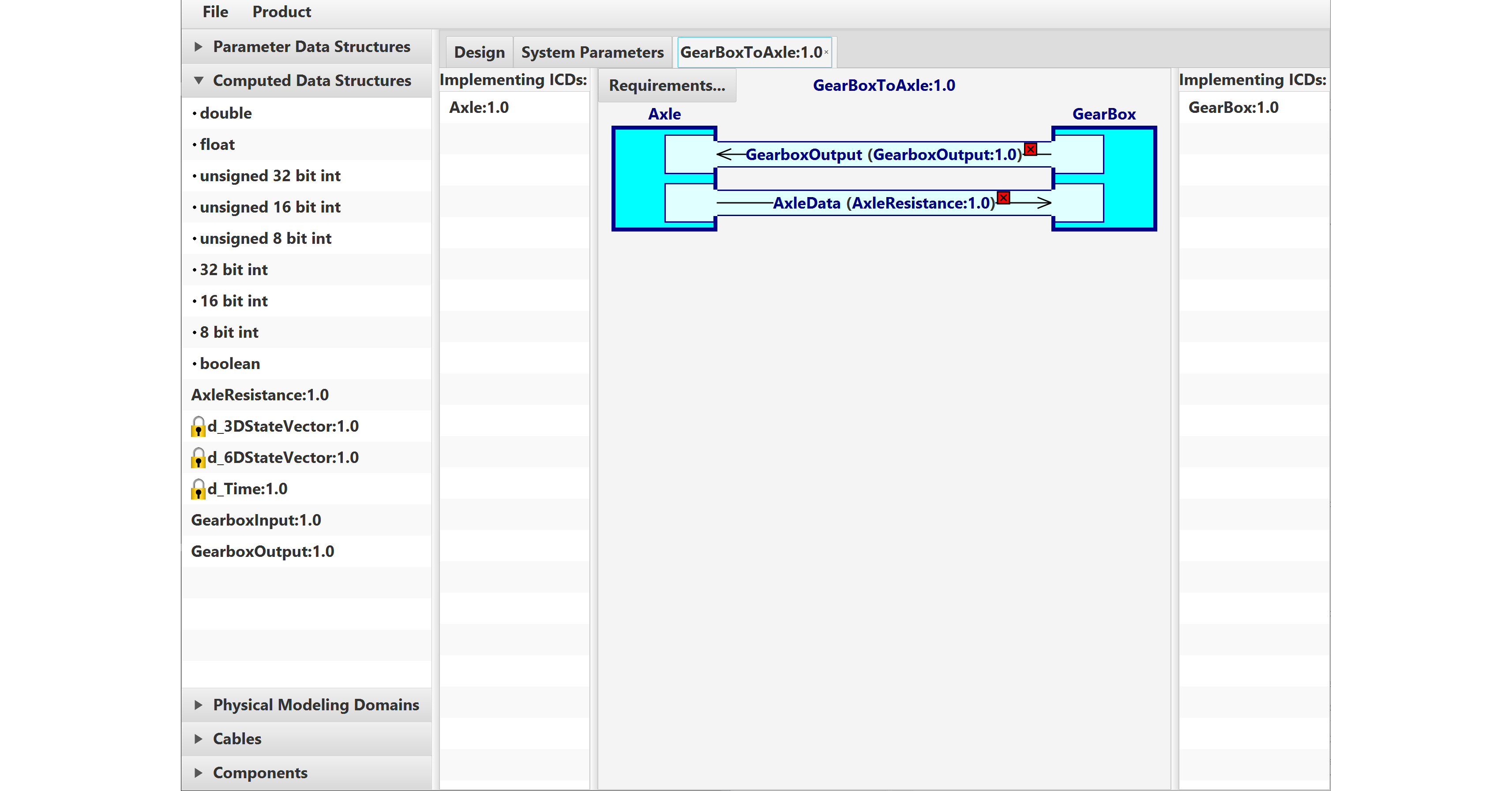
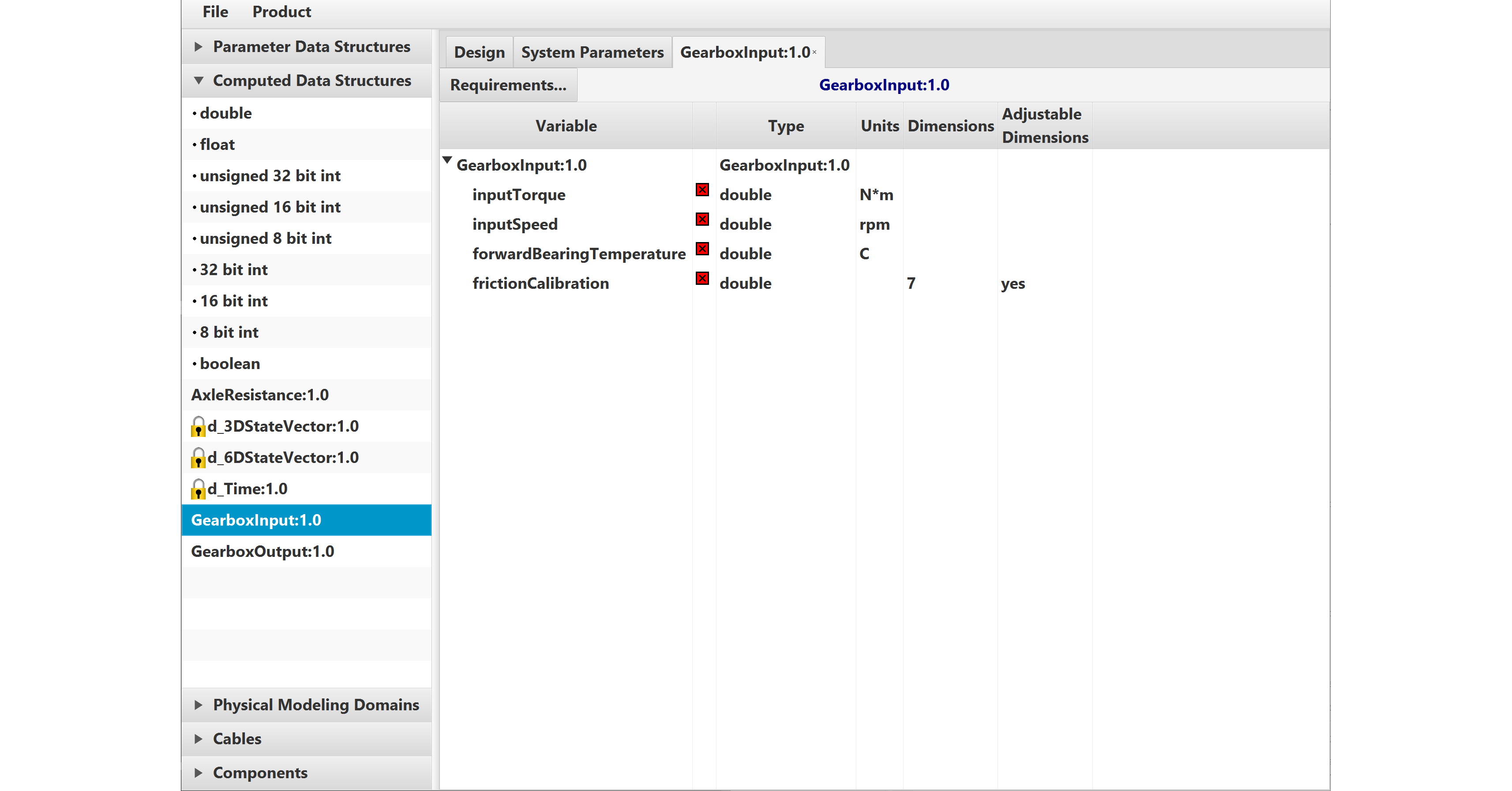
The data that is carried by the cables is defined graphically using drag-and-drop:
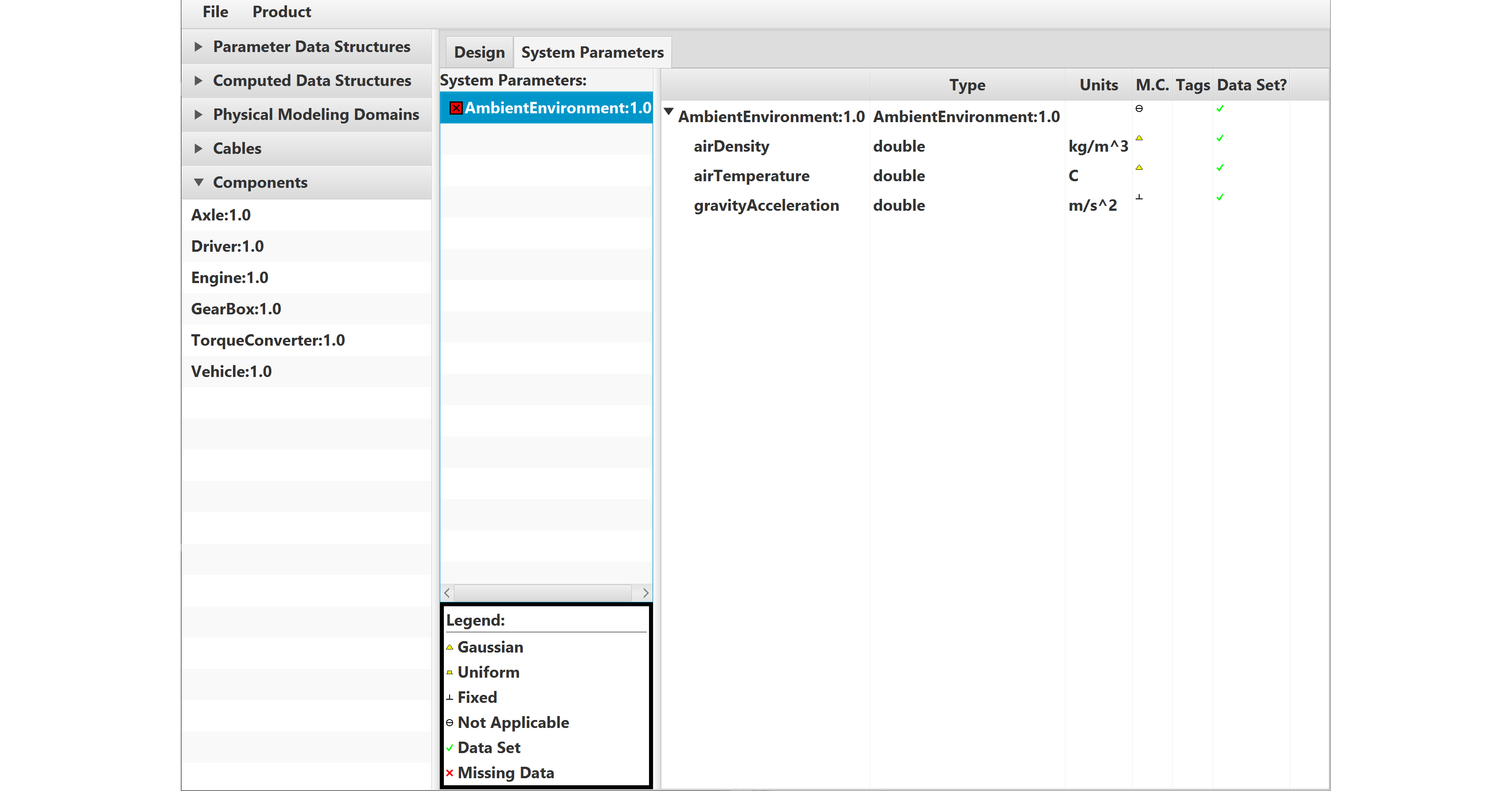
You’ll also want to define shared parameters, to ensure the team is using a common parameter set:
Inevitably, your design will evolve as your project grows from its initial stages to a high-fidelity simulation. Simply re-visit SystemDesigner as needed to update and refine the design:
The above steps fully define the simulation design and the component interfaces. Notice that there are no explicit ICDs in this process. SystemDesigner focuses on the system-level design, and ComponentGuide translates it into ICDs. I’ll describe that in my next blog post.
