Tour of SystemBlend™, Part 2: ComponentGuide

by | Dec 6, 2021 | Product Description

This is the second of a three-part series describing SystemBlend™ and how it works. In this post, I’ll describe ComponentGuide.
In my previous article, I described how the simulation team graphically develops the design database using SystemDesigner. This article describes how a subsystem model developer uses ComponentGuide to streamline component development.

Imagine you’re developing a subsystem model for inclusion into a larger simulation. This could be a thruster model for a satellite simulation, a transmission model for an automotive simulation, or perhaps an interceptor model for a Ballistic Missile Defense System. Your team has captured the system-level design of the simulation, and you are in charge of building the subsystem.

You start by launching ComponentGuide. It first asks you which ICD in the design database you plan to implement:
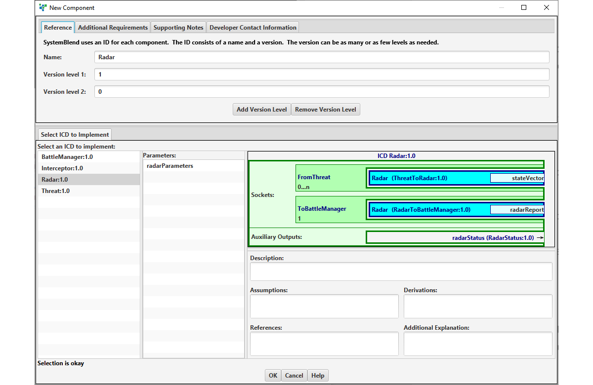
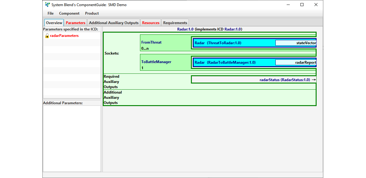
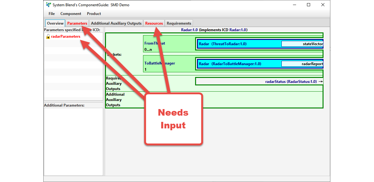
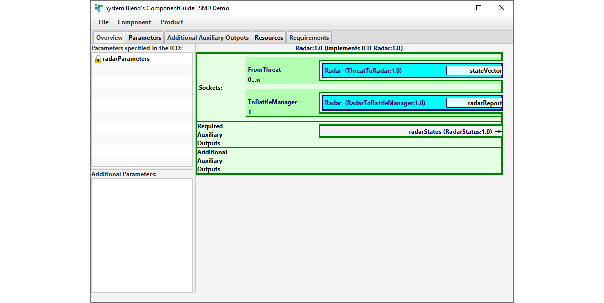
Once the ICD is selected, a graphical representation of the component is displayed:
ComponentGuide guides you by displaying in red anything that needs attention:
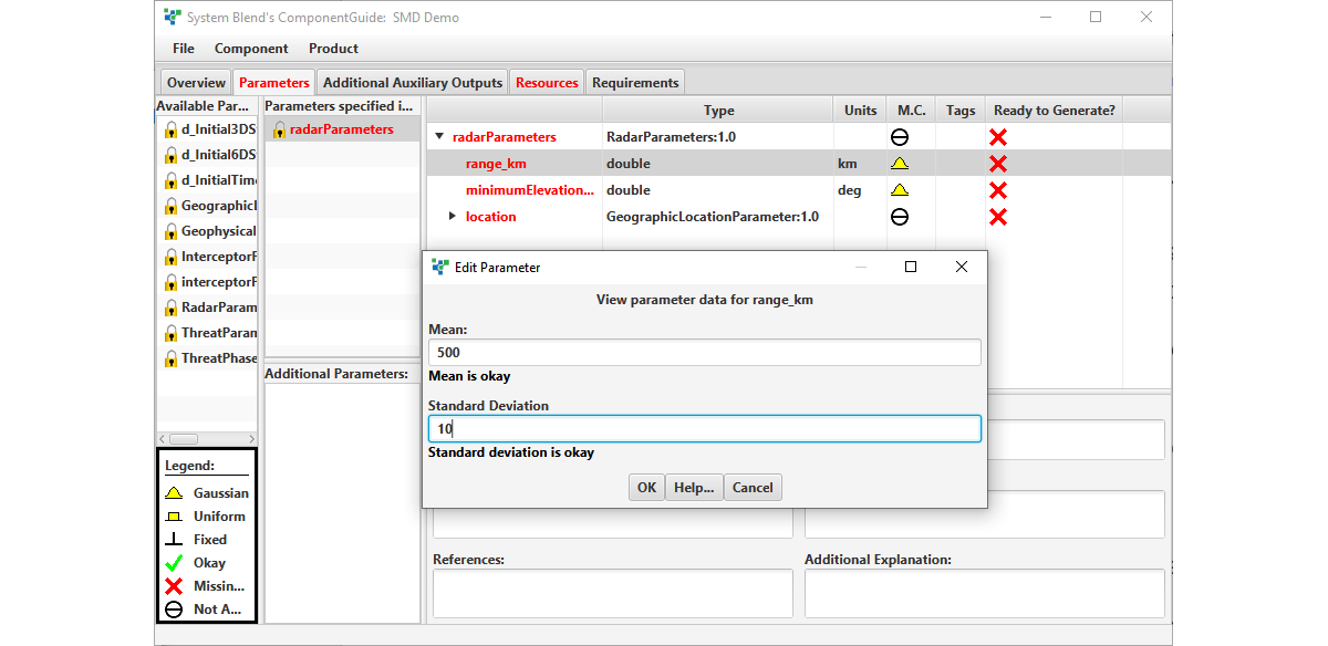
The design database specifies what parameters define the subsystem model, and the model developer provides values for these parameters:
These parameters can be adjusted in the integrated simulation, unless otherwise indicated.

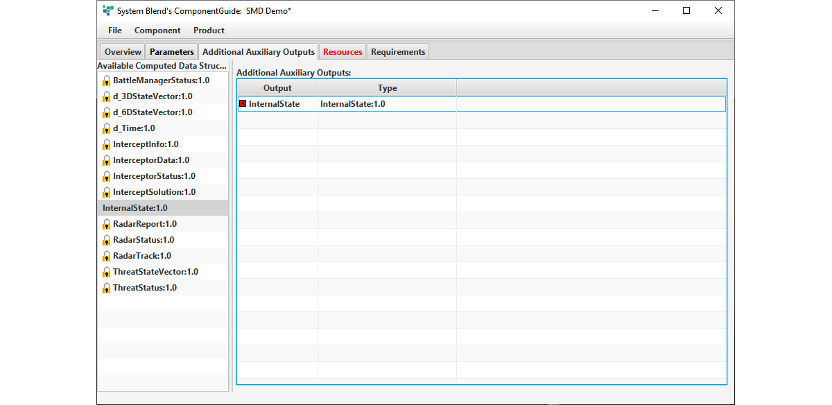
You can optionally specify additional outputs for analysis, test, debugging, or any other purpose:
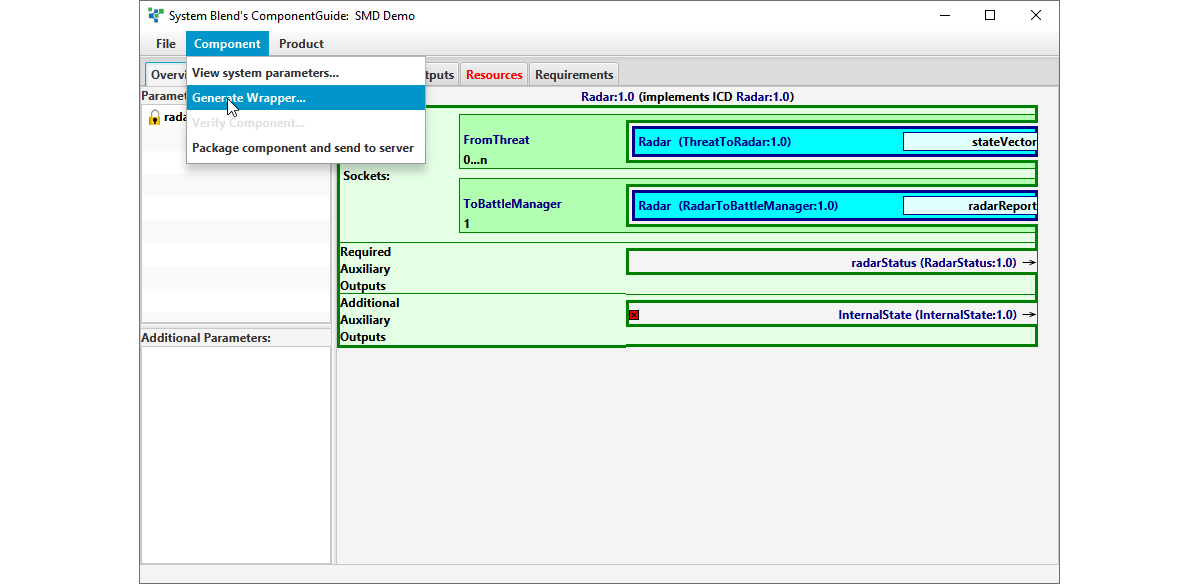
Once your component is fully defined, you can generate a wrapper with a simple menu item:
This will automatically generate:

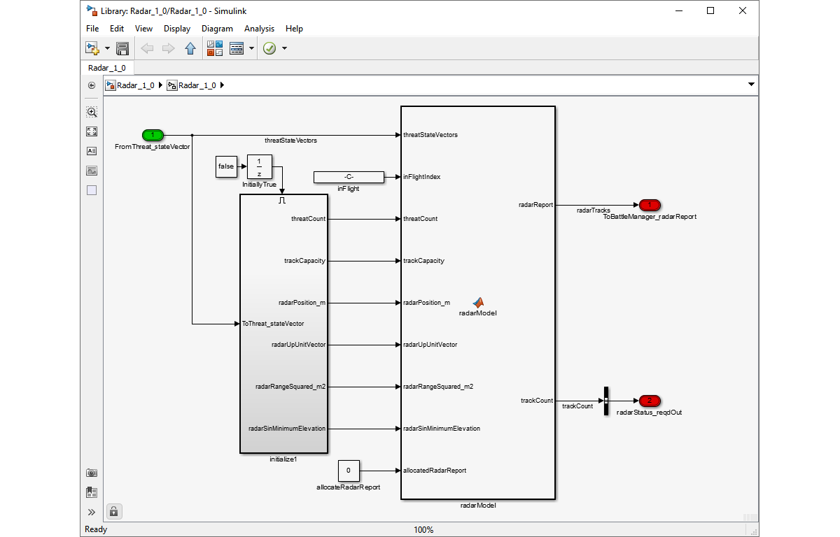
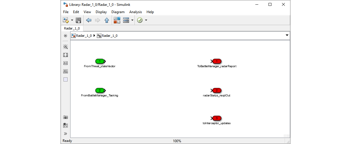
  • A Simulink library block that exactly implements the specified interfaces, but is otherwise empty:
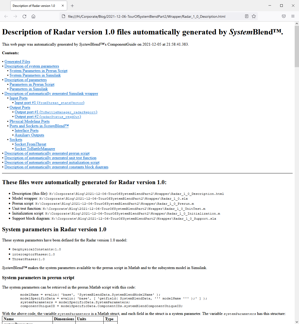
  • A user’s guide that is specific to the particular model, and specifies all of the interface details:
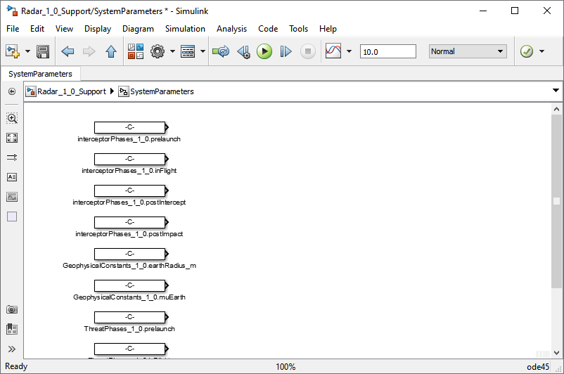
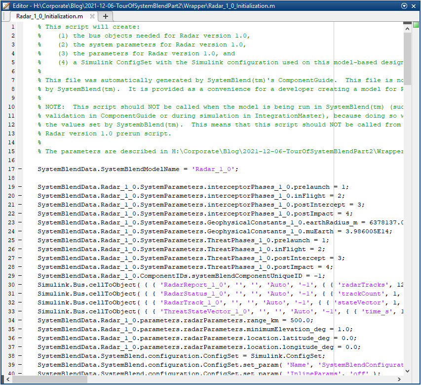
    • Support files to aid in the development:
    • Support Library
      Support Script
      At this point, you exit ComponentGuide and work in Simulink. Open the automatically generated wrapper and use the automatically generated user’s guide to add the simulation behavior:
      Because you are working outside of ComponentGuide, you are free to use whatever tools and techniques you prefer to develop the models; SystemBlend does not constrain you.

      Once the model is complete, return to ComponentGuide. Load the resources for the model:
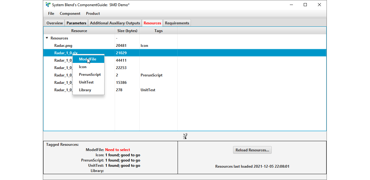
      The model’s resources can include any file that the model might need, such as scripts, library files, data files, image files, or any other file.

      Finally, ask ComponentGuide to verify the model:
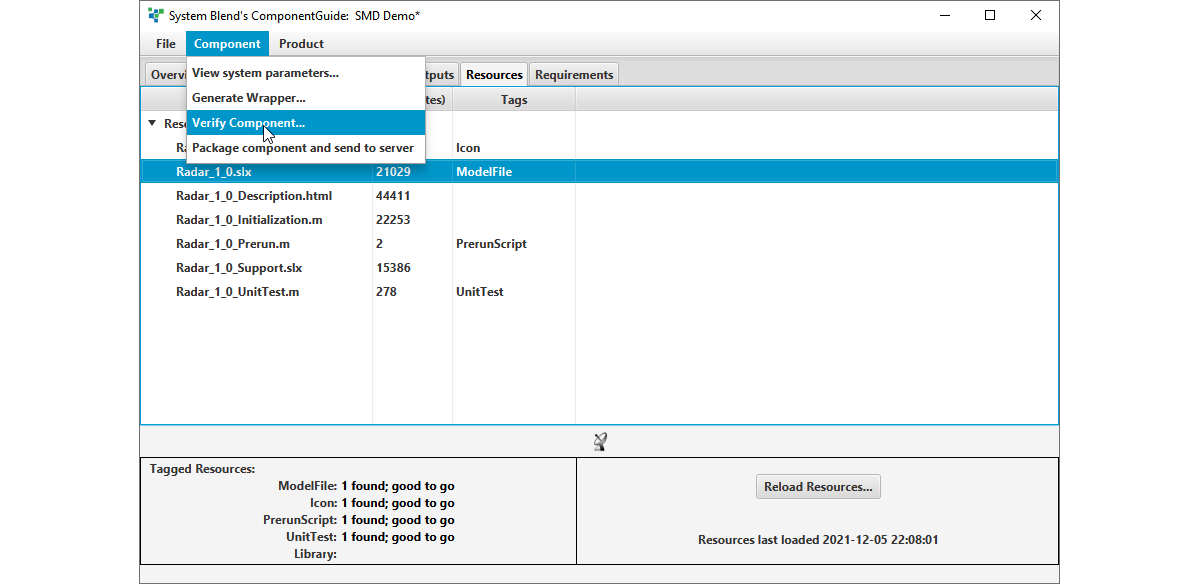
      This will ensure that the model complies with its ICD, by performing these automated tests:

      1. A static analysis of the model to confirm its interfaces,
      2. Simulink’s ‘model update’ facility to confirm viability of the model, and
      3. A user-supplied unit test.

      Once the model has been verified, package it for delivery to the full simulation:
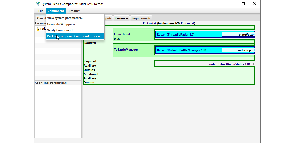
      ComponentGuide manages the housekeeping to ensure compatibility of the component, while you focus on the actual engineering work.

      In my next article, I’ll describe how IntegrationMaster integrates the components using simple drag-and-drop.

      Request More Information

      Contact Us To Learn More